
Arduino Uno is one of the most popular development boards in Electronics and Embedded system projects. This development board is beginner-friendly and easy to use. It is mostly used by students, engineers, and hobbyists.
Table of Contents
Introduction to Arduino Uno
Arduino Uno is the most popular microcontroller development board used by students, engineers and hobbyists. It is used for learning electronics, programming, and building smart projects. This development board uses the Atmrga328p microcontroller. This Arduino Uno can be connected to different types of sensors, display drivers, actuators, and relays for building useful innovations.
Arduino Uno is used in simple automation projects, robotics, IoT, and embedded systems. This is a plug-and-play development board that can easily make connections, and it can be easily programmed with the Arduino IDE.
It is beginner-friendly and also it availabe in low cost, it is open source, and it has a large community support for the projects and forums
History of Arduino
Arduino was first developed in Italy in 2005 at the Interaction Design Institution Ivrea. It was created to provide an affordable and easy-to-learn platform for students and beginners to learn electronics and programming. Before Arduino, microcontroller programming was very difficult for many people.
Over a period of time, Arduino became very poupler ad i tbecome opensource design, a low-cost and simple programming environment.
Features of Arduino Uno
Arduino Uno is one of the most popular microcontroller boards because of its simple design, powerful features, and beginner-friendly interface. It provides all the essential functionalities needed for electronics and programming projects. Below are some important features of Arduino Uno.
1. Atmega328p Microcontroller
Arduino UNO is based on the Atmega328p Microcontroller, it acts as the brain of the board, which will control the Sensors and output devices like Relay, Valve, motor, etc
2. Digital input and output pin
The Arduino Uno development board has 14 digital input and output pins, which are named from D0 to D13. Which can be used for reading environmental changes using sensors and and contol the output devices like relays, drivers and controllers. Out of these 14 pins, 6 pins are supporting PWM (pulse-width modulation), which will be used for controlling output using pulse-like brightness and motor speed.
3. Analog Pins
Arduino Uno has 6 Analog input pins named A0 – A5, which are used to receive analog signal input from sensors like temperature sensors, gas sensors, etc.
4. Easy programming
The Arduino Uno can be easily programmed by usb cable. This is beginner-friendly and easy to program using the Arduino IDE. The program can be written in the Arduino IDE us C++ programming language.
5. Power supply
The Arduino Uno board runs with a 5V DC supply. It can be powered by using a USB cable when it is in standalone if it works with heavy loads, like multiple it has a power jack used to power the board. It has a 5V voltage regulator to provide a constant power supply to the development board.
6. Serial communication
The Arduino Uno supports multiple communication protocols to interact with sensors, displays, and other microcontrollers
- UART (Universal Asynchronous Receiver Transmitter)
- SPI (Serial Peripheral Interface)
- I2C ( Inter-Integrated Circuit )
Arduino Uno Specifications
| Specification | Details |
|---|---|
| Microcontroller | ATmega328P |
| Operating Voltage | 5V |
| Input Voltage (Recommended) | 7V – 12V |
| Input Voltage (Limit) | 6V – 20V |
| Digital I/O Pins | 14 |
| PWM Pins | 6 (Pins 3, 5, 6, 9, 10, 11) |
| Analog Input Pins | 6 (A0 – A5) |
| DC Current per I/O Pin | 20 mA |
| DC Current for 3.3V Pin | 50 mA |
| Flash Memory | 32 KB |
| SRAM | 2 KB |
| EEPROM | 1 KB |
| Clock Speed | 16 MHz |
| USB Interface | USB Type-B |
| Communication Protocols | UART, SPI, I2C |
| Length | 68.6 mm |
| Width | 53.4 mm |
| Weight | Approximately 25 g |
Pin Diagram
In Arduino Uno, there are different types of pins available, which have individual functionalities like digital analog, communication, etc. The Arduino Uno pin diagram is essential to make connections, configuration, and to make projects.
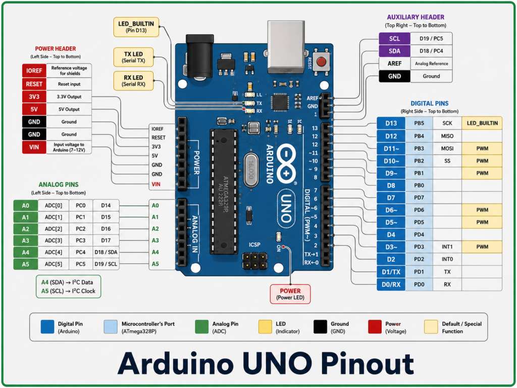
Digital pins
In Arduino Uno, there are 14 digital pins; these pins can be configured as either digital input or digital output. The digital pins are numbered as D0 to D13. If it is configured as an output, we can control the output devices like relay actuators, etc. If it is configured as an input, we can read the digital values from the sensors.
PWM Pins
it the digital pins, there are 6 special functionality pins are availabe this pins support PWM (pulse-width modulation ) it ia a analog like output it generate pulses nad the pulse can be used for controlling the speed of the motor, brightness of led using the drivers. The digital pins that support the PWM are listed below.
- D3
- D5
- D6
- D9
- D10
- D11
Analog pins
The Arduino Uno has 6 analog pins that can be used to read the analog values from the sensor. This can be numbered as A0 to A5.
Power pins
The power pins are used to give a power supply to the development board. It has several power pins listed below
| Pins | Descriptions |
| VIN | Used to supply External supply tor the Arduino Uno |
| 5V | Regulated 5v power suppy |
| GND | Ground Connection |
| 3.3V | Regulated 3.3V power supply |
UART Pin
UART ( Universal Asynchronous Receiver Transmitter ), which is a serial communication protocol to connect, send and receive data.
| Pins | Descriptions |
| TX (pin 1 D1 ) | useed to transmitt data |
| RX ( pin 0 D0 ) | used to receive data |
The UART communication is used in different applications like Serial monitor communication, Bluetooth module, GSM module, etc.
SPI
SPI Serial (Serial Peripheral Interface ), which is used for high-speed communication with the external devices, this SPI Communication protocol needs a clock for operation.
| Pins | Descriptions |
| MISO D12 | Maste In Slave Out |
| MOSI D11 | Master Out Slave In |
| SCK D13 | Serial Clock |
| SS D10 | Slave Select |
ICSP Pins
ICSP ( In-Circuit Serial Programming pins ) is used for direct microcontroller programming and boot loader installation
Components of the Arduino Uno Board
Arduino Unno has several important components that work together to provide processing power management, and communication. Understanding the use and function of every component will help beginners understand the working of the Arduino Uno.
ATmega328P Microcontroller
ATmega328p is the main microcontroller in the Arduino Uno board, which acts as the brain of the Arduino Uno, managing all the programs uploaded to it and handling all the inputs and controlling all the outputs.
USB Type – B Connector
The USB Connector is used to connect the Arduino Uno to the Computer or laptop. It will be mainly used for powering the Arduino Uno, uploading a program to arduino uno and making serial communication between the Arduino Uno and the computer
DC Power jack
The DC power jack is used to give the power supply to the Arduino Uno using charging adapters or a battery source. The power supply given to the Arduino Uno must be 7V – 12V. Excessive voltage may damage the Board.
Voltage Regulator
The Voltage regulator is used to give a stable power supply to the entire board. The voltage regulator will help convert the higher voltages to a constant 5V to ensure the stable operation of the board and protect the board from damage due to higher voltage
Reset Button
The Reset Button is used to restart the Microcontroller and run the entire program from the beginning. When you press the reset button, the Arduino Uno will stop the current running operation and start running the uploaded program from the beginning.
Crystal Oscillator
The Arduino Uno uses the 16 MHz crystal oscillator to generate the clock. The clock pulse generated by the oscillator will be used for the speed of the program execution and time management in the microcontroller. If the clock is not available, then the microcontroller will no executerogram and operation properly.
ATmega16U2 USB-to-Serial Converter
The ATmega16U2 chip in the Arduino Uno is used to make communication between the USB and the ATmega328p microcontroller chip. It will be used to convert the data from the USB cable into serial communication signals.
How to Program Arduino Uno?
Programming the Arduino Uno is very simple. It will need a computer or laptop,usb type b cable and arduuino uno and Arduino IDE. I will give the step-by-step instructions to program the arduio uno
Download and install Arduino IDE
To download the Arduino IDE, first go to your browser and search for Arduino IDE, then click and open the official Arduino.cc website, click the product option in the menubar, and click Arduino IDE. You can also download the official Arduino IDE by clicking the button below.
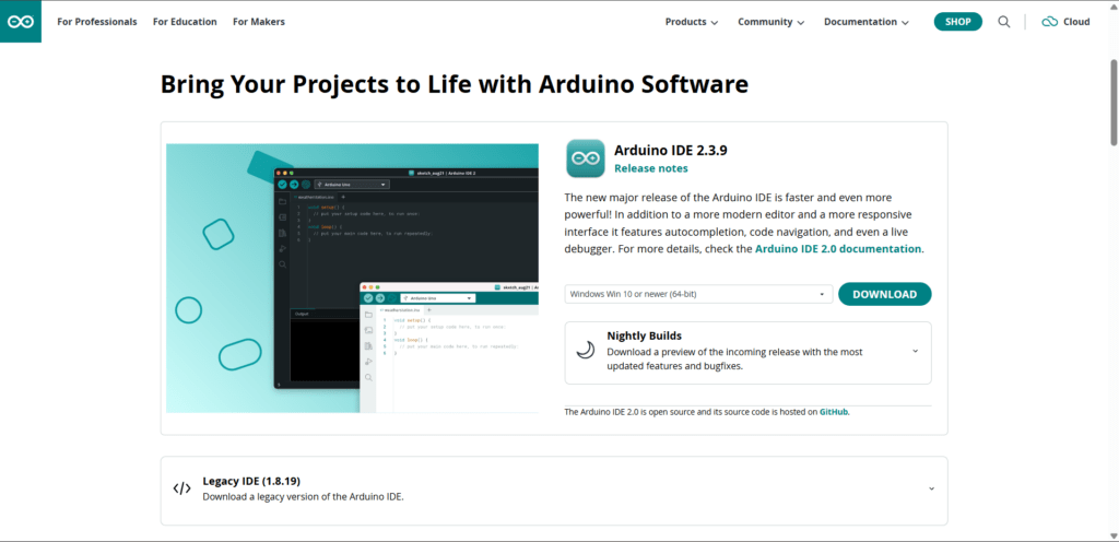
On this page, you can see the Arduino IDE to download it first select you os annd then click download. Once the file is downloaded completely you can install the IDE by following the steps.
First, click and open the IDE file,
then a pop-up will show for the licence agreement, accept this.
Then a popup show for select the user select the user type and click next.
Then click Agree,
choose the installation path, and click Next
Now the Arduino IDE installation has started; once it is completed, it will be ready to use.
How to connect the Arduino Uno to a computer?
Follow the steps to connect the Arduino Uno to the pc without any issue.
first conce to usb type B cable between the Developement Board and th pc. Open your IDE
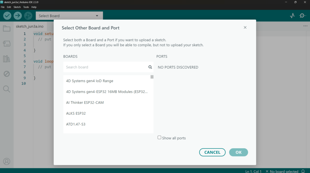
In this click, select the Select Board dropdown and click Select Board and Port. A pop-up will be shown to choose the Board and Ports. Type Arduino Uno and select it. For the port, it will show the Arduino Uno connected port. You can select it
NOTE: Selecting the board and port is important; if you select the wrong it will not work, and unable to upload the program to the Arduino Uno
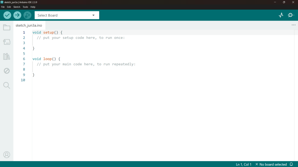
Now you can write the program for the Arduino Uno as required for the project. The program can be written with the help of 2 basic functions: setup() and loop(). In setup (), we will configure the pin, which is operating as an input or output. In a loop, it will continuously execute the logic inside it to perform tasks and operations.
Once you complete your program, click the (✓) to verify the program. It will check the error in the program. If no error occurs, then
After verifying the program, click the (→) button in the toolbar to upload the program to the Aeduino uno
One program was uploaded to the Board successfully, then it showed that the upload was successful in the Serial monitor
Application of the Arduino Uno
It has many applications in electronics and automation; it is used for controlling LEDs, reading sensor values, operating motors, building home automation systems, and IoT applications.
Disadvantages of Arduino Uno
- Limited memory capacity
- Low processing speed compared to advanced boards
- Limited number of input/output pins
- No built-in Wi-Fi, No built-in Bluetooth
- Cannot directly control high-power devices
- External modules are needed for wireless projects
- Not suitable for complex multitasking
- Not ideal for industrial-level applications
- Limited analog input pins
- Requires extra driver circuits for motors and relays
- Not suitable for image processing or high-speed applications
- Limited storage for large programs
- Less powerful than Raspberry Pi, ESP32, and other advanced boards
- Mostly suitable for learning, prototyping, and small projects