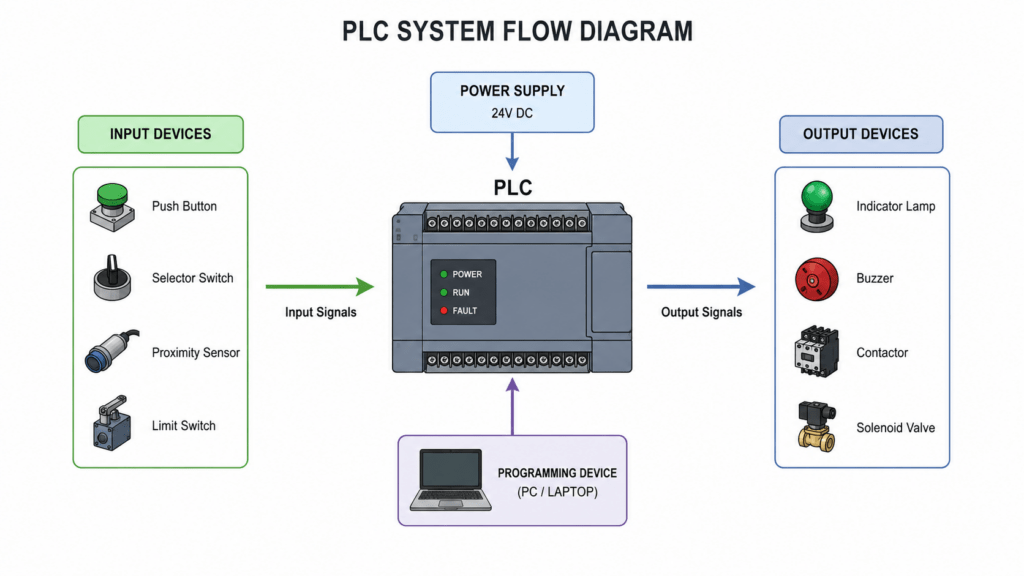
Simple PLC working Flow Diagram
Automation, PLC

What is a PLC ( Programmable Logic Controller )?

PLC -Definition, application, advantages, disadvantages In modern industries, PLC plays a major role in controlling the machinery without human intervention, with on-time and without errors, it will give a great revolution to the manufacturing, assembling, and packing to control and monitor the process continuously What is PLC? A PLC is a Programmable Logic Controller, it is a rugged industrial computer used to automate processes in the industries, it will control and monitor the state of the machinery continuously. PLC are designed to withstand heavy industrial environments like dust, heat, vibration, moisture and electrical noise. it continously monitor thesignal from the input service and controls the output for the logic programmed in it Defination PLC is a device which continiously monitor the signal from the input device like sensors, switches, push buttons, and controls the output devices, like valves, motors, and relays according to the logic Simple PLC workflow INPUT ——-> PROGRAM LOGIC ———-> OUTPUT In the flow, the input is the signal from the devices like switch push buttons and sensors, and the program logic is the code written in the PLC with different types of programming languages, like ladder logic, functional block diagram, instruction list, etc in the output, the device can be controlled by the PLC according to the Logic and the input signal. It controls devices like motor valve, relay, etc Application of PLC PLCs are widely used in industrial automation to control machines, processes, and production systems. Their reliability, flexibility, and ability to operate in harsh environments make them essential in many industries. The PLC is widely used in most of the inddustriesfor the automate the process, controlling the machines. Advantage of plc Disadvantage

Arduino Uno Complete Guide
Arduino Tutorials, Electronics, Embedded System

Arduino Uno Complete Guide: Features, Pinout, Programming & Projects

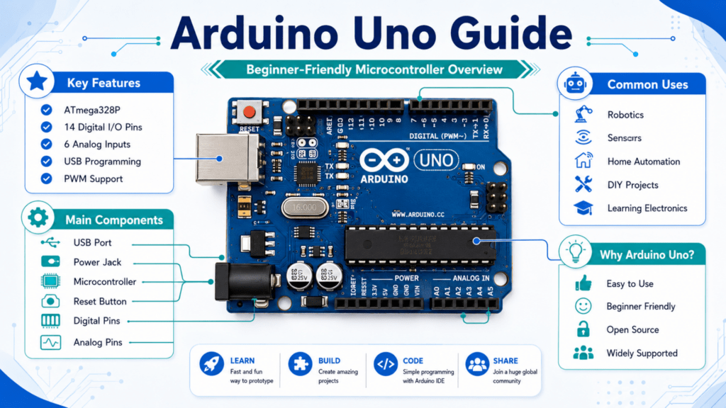
Arduino Uno is one of the most popular development boards in Electronics and Embedded system projects. This development board is beginner-friendly and easy to use. It is mostly used by students, engineers, and hobbyists. Introduction to Arduino Uno Arduino Uno is the most popular microcontroller development board used by students, engineers and hobbyists. It is used for learning electronics, programming, and building smart projects. This development board uses the Atmrga328p microcontroller. This Arduino Uno can be connected to different types of sensors, display drivers, actuators, and relays for building useful innovations. Arduino Uno is used in simple automation projects, robotics, IoT, and embedded systems. This is a plug-and-play development board that can easily make connections, and it can be easily programmed with the Arduino IDE. It is beginner-friendly and also it availabe in low cost, it is open source, and it has a large community support for the projects and forums History of Arduino Arduino was first developed in Italy in 2005 at the Interaction Design Institution Ivrea. It was created to provide an affordable and easy-to-learn platform for students and beginners to learn electronics and programming. Before Arduino, microcontroller programming was very difficult for many people. Over a period of time, Arduino became very poupler ad i tbecome opensource design, a low-cost and simple programming environment. Features of Arduino Uno Arduino Uno is one of the most popular microcontroller boards because of its simple design, powerful features, and beginner-friendly interface. It provides all the essential functionalities needed for electronics and programming projects. Below are some important features of Arduino Uno. 1. Atmega328p Microcontroller Arduino UNO is based on the Atmega328p Microcontroller, it acts as the brain of the board, which will control the Sensors and output devices like Relay, Valve, motor, etc 2. Digital input and output pin The Arduino Uno development board has 14 digital input and output pins, which are named from D0 to D13. Which can be used for reading environmental changes using sensors and and contol the output devices like relays, drivers and controllers. Out of these 14 pins, 6 pins are supporting PWM (pulse-width modulation), which will be used for controlling output using pulse-like brightness and motor speed. 3. Analog Pins Arduino Uno has 6 Analog input pins named A0 – A5, which are used to receive analog signal input from sensors like temperature sensors, gas sensors, etc. 4. Easy programming The Arduino Uno can be easily programmed by usb cable. This is beginner-friendly and easy to program using the Arduino IDE. The program can be written in the Arduino IDE us C++ programming language. 5. Power supply The Arduino Uno board runs with a 5V DC supply. It can be powered by using a USB cable when it is in standalone if it works with heavy loads, like multiple it has a power jack used to power the board. It has a 5V voltage regulator to provide a constant power supply to the development board. 6. Serial communication The Arduino Uno supports multiple communication protocols to interact with sensors, displays, and other microcontrollers Arduino Uno Specifications Specification Details Microcontroller ATmega328P Operating Voltage 5V Input Voltage (Recommended) 7V – 12V Input Voltage (Limit) 6V – 20V Digital I/O Pins 14 PWM Pins 6 (Pins 3, 5, 6, 9, 10, 11) Analog Input Pins 6 (A0 – A5) DC Current per I/O Pin 20 mA DC Current for 3.3V Pin 50 mA Flash Memory 32 KB SRAM 2 KB EEPROM 1 KB Clock Speed 16 MHz USB Interface USB Type-B Communication Protocols UART, SPI, I2C Length 68.6 mm Width 53.4 mm Weight Approximately 25 g Pin Diagram In Arduino Uno, there are different types of pins available, which have individual functionalities like digital analog, communication, etc. The Arduino Uno pin diagram is essential to make connections, configuration, and to make projects. Digital pins In Arduino Uno, there are 14 digital pins; these pins can be configured as either digital input or digital output. The digital pins are numbered as D0 to D13. If it is configured as an output, we can control the output devices like relay actuators, etc. If it is configured as an input, we can read the digital values from the sensors. PWM Pins it the digital pins, there are 6 special functionality pins are availabe this pins support PWM (pulse-width modulation ) it ia a analog like output it generate pulses nad the pulse can be used for controlling the speed of the motor, brightness of led using the drivers. The digital pins that support the PWM are listed below. Analog pins The Arduino Uno has 6 analog pins that can be used to read the analog values from the sensor. This can be numbered as A0 to A5. Power pins The power pins are used to give a power supply to the development board. It has several power pins listed below Pins Descriptions VIN Used to supply External supply tor the Arduino Uno 5V Regulated 5v power suppy GND Ground Connection 3.3V Regulated 3.3V power supply UART Pin UART ( Universal Asynchronous Receiver Transmitter ), which is a serial communication protocol to connect, send and receive data. Pins Descriptions TX (pin 1 D1 ) useed to transmitt data RX ( pin 0 D0 ) used to receive data The UART communication is used in different applications like Serial monitor communication, Bluetooth module, GSM module, etc. SPI SPI Serial (Serial Peripheral Interface ), which is used for high-speed communication with the external devices, this SPI Communication protocol needs a clock for operation. Pins Descriptions MISO D12 Maste In Slave Out MOSI D11 Master Out Slave In SCK D13 Serial Clock SS D10 Slave Select ICSP Pins ICSP ( In-Circuit Serial Programming pins ) is used for direct microcontroller programming and boot loader installation Components of the Arduino Uno Board Arduino Unno has several important components that work together to provide processing power management, and communication. Understanding the use and function of every component will help beginners understand the working of

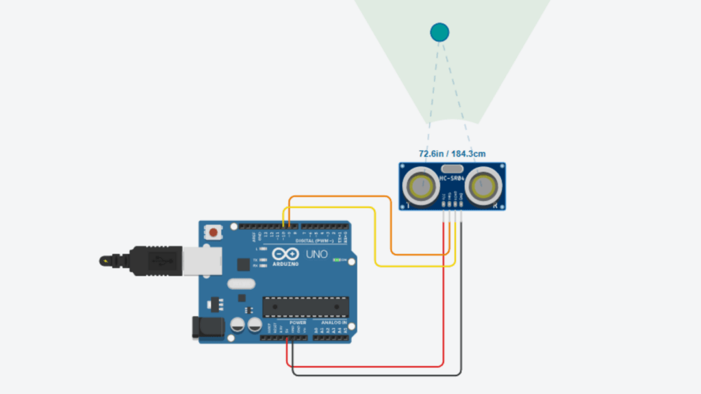
ultrasonic sensors Arduino Uno Wiring Diagram
Arduino Tutorials, Electronics

Ultrasonic Sensors: How to Interface HC-SR04 with Arduino Uno (Step-by-Step Guide)

Learn how to interface the HC-SR04 Ultrasonic sensors to the Arduino Uno with simple wiring and code. Here I will explain a step-by-step guide with wiring connection, how to program, how to boot program and how to test. Introduction In this tutorial, we will learn how to interface the HC-SR04 Ultrasonic sensor to the Arduino Uno and the components required for the Arduino Distance Calculation. Ultrasonic Sensors The Ultrasonic Sensor is an electronic device that uses sound waves to detect objects and measure distance. This sensor has two processes to detect and measure by sending sound waves and receiving the echo when they bounce back from the objects. The ultrasonic sensors are used in applications like Automatic Parking Systems, Obstacle detection, and industrial automation, etc. Components The main components required for this tutorial are, Arduino Uno Arduino Uno is a development board that works with the Atmega328p microcontroller chip. It is a beginner-friendly development board. It has 14 Digital I/O pins, namely D0 – D13, and 6 analog pins, namely A0 – A5. HC-SR04 UltraSonic Sensor The HC-SR04 sensor is mainly used for distance measurement and obstacle detection in electronic and Arduino projects. It is a low-cost, highly accurate and beginner-friendly ultrasonic sensor it has 4 pins. They are VCC – this pin is used to give the supply voltage to the sensor; it is supplied with +5V GND – this pin is connected to the GND TRIGGER – this pin is used to send ultrasonic sound waves ECHO – this pin is used to receive the reflected ultrasonic waves Connection details pin connection Ultrasonic sensor Arduino Uno VCC + 5V TRIGGER D9 ECHO D10 GND GND programing Arduino Uno Programming Arduino Uno is an easy thing, and we can do it in simple steps. Follow the steps below to program without any issues Step 1: First, we need the Arduino IDE. If you don’t have Arduino IDE, then you need to download and install it by visiting Arduino.cc Step 2: After setting up the software, you need to create a new sketch by follow this step in the menu > click Files > Click Create New Sketch, then give a name to it and save it. Step 3: Now you can write the program in ide, for this tutorial, I give the code below. You can copy and paste it. Step 4: Verify the program for errors by clicking the verify button in the toolbar. Step 5: If it has no errors, then we proceed to boot the program to the Arduino IDE. Step 6: Connect the Arduino Uno and PC by using the Programming cable. Step 7: To boot the program too arduino uno, first select the port and device. Step 8: Click the upload button in the toolbar to boot the program to the Arduino Uno.

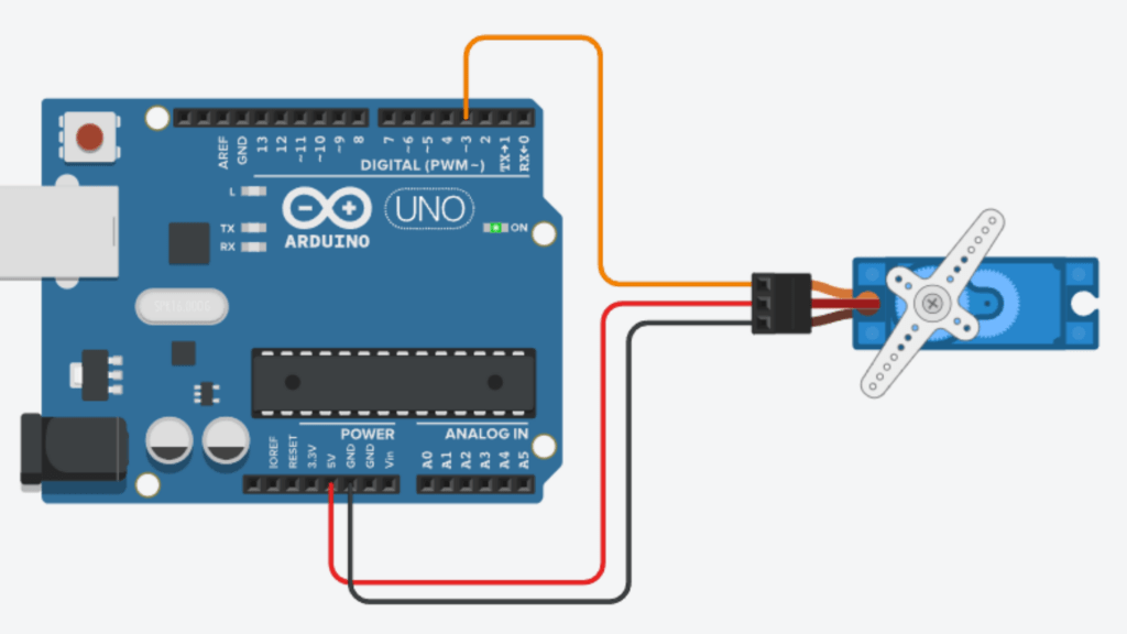
Servo Motor with Arduino Uno Wiring Diagram
Arduino Tutorials, Electronics

Control a Servo Motor with Arduino Uno Using Simple Code

Introduction In this tutorial, we will learn how to control a servo motor with Arduino Uno. Servo motors are used in various applications like robotics, etc. Components components used in this project are, Arduino Uno Arduino Uno is a Microcontroller board that uses Atmega 328p. This development board has 14 digital I/O pins and 6 Analog pins, the arduino uno has beginner friendly and best for starters. which is mostly used by students, engineering students and hobbyists. Servo Motor A servo motor is a special type of motor that can be used for rotating with a specific angle and rotating with high accuracy. The servo motor is different from a normal electrical motor because a normal motor runs continuously, but a servo motor rotates with a specific angle, 0 °, 30 °, 45 °, 90 °, etc. The servo motor has 3 pins, namely VCC, GND and Signal VCC – this pin is used to supply 5V to the Servo motorGND – this pin is connected to the ground (negative)SIGNAL – this pin is used to provide the signal for the operation of the servo motor Circuit Connection The connection for this tutorial is very simple Servo Motor Arduino Uno VCC 5V GND GND SIGNAL D3 Step 1: Connect the circuit as per the Schematic and Circuit connection details Step 2: Connect the Arduino Uno programming cable to the PC Step 3: Open Arduino IDE and copy and paste the program given below

LED Blinking using Arduino Uno
Electronics

Led blinking using Arduino Uno in Thinker CAD

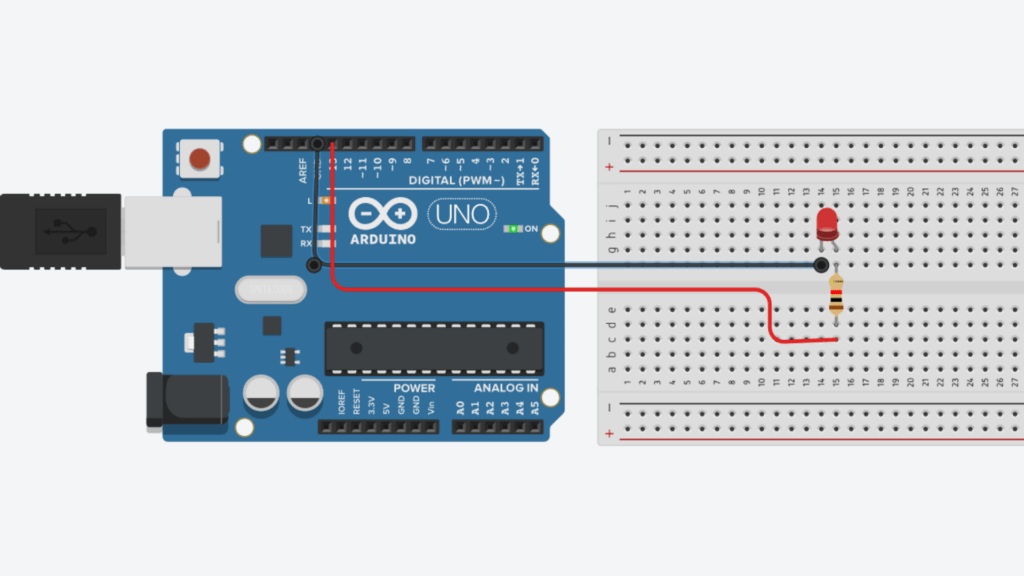
Hi Learners, in this project tutorial, we will learn how to do the LED blinking using Arduino Uno in the Thinker CAD introduction LED blinking is a very beginner project in electronics and embedded systems, it is just like the “Hello World” program in programming languages. It will help to learn the basic concepts like digital output and simple circuit connections. Components required Arduino Uno Arduino Uno is a very basic and beginner-friendly microcontroller development board that is used for starter projects by students, engineers, and hobbyists. The Arduino Uno development board has an Atmega328p microcontroller chip . It has 14 digital I/O Pins named D0 – D13. It has 6 Analog Pins named A0- A5. This Arduino Uno board has a USB converter built in, so we can easily boot the program to the Arduino. It can be powered using 7 – 12V DC Voltage. If we connect to the overvoltage source, it may damage the development board LED – Light Emitting Diode A light-emitting diode, which is commonly called an LED, converts the electrical current into light energy using the principle of electroluminescence. When the electric current passes through the semiconductor material, the electrons recombine with the hole, producing the excess energy, which is called a photon Resistor A resistor is a passive component that is used to limit the flow of current in an electrical circuit. It will work by limiting the current flow and releasing it in the form of heat energy Now we can do a simple calculation for choosing the resistor for this circuit. You can learn more about how to select the correct resistor by reading the post Now, the step-by-step guide to do the LED blinking tutorial Circuit Connection Step 1: Connect the resistor to the Digital pin D13 in Arduino Uno Step 2: Connect the resistor’s other end to the LED Anode pin ( + ) Step 3: Connect the Arduino Uno GND pin to the LED cathode pin Step 4 : Connect the Arduino cable to the Arduino Uno and PC Step 5: Now write a program to blink the LED. Open the Arduino IDE, copy and paste the Arduino program below Step 6: Now select the Board and Port, then click the verify button to check the code for correctness Step 7: Upload the code to the Arduino Uno board Once the program booted on the Arduino Uno, once the program successfully booted, the LED will start blinking continuously For the above program, the LED will be ON for 1 second and OFF for 1 Second. You can change the duration by changing the value inside the function delay(1000). If you need it for 3 seconds, then change it to delay(3000). I will provide the LED Blinking Using Arduino Uno thinker CAD project

Led Resistor calculation
Electrical, Electronics

LED resistor: How to choose the Right Resistor for an LED (Simple Formula & Examples)

LED – The Light Emitting Diode that is mostly used in electrical and electronics circuits. the led are mostly used for indication, for used inn decoratiove in decorative lamps, led panels are used for advertising panels. LED Defination An LED is a type of Semiconductor device that emits light when an electric current flows through it. The LED will convert the electric current to light with the working principle of electroluminescence. How an LED is constructed The LEDs are constructed using the semiconductor materials arranged in a specific pattern that will help to allow light to be emitted when power is applied to them. The semiconductor materials used in the LED are The semiconductor materials used for the construction will determine the colour of the LED P – N junction The semiconductor use in the construction of the are divided into two regions The P-type semiconductor is positive, and it contains the majority of holes. The N – type semiconductor is negative, and it contains the majority of electrons. These two different types of semiconductor material join together to form a junction, which is called a PN Junction. This is essential for the working of the LED. The area around the junction is called the active region. When the current flows through the junction, it will emit light from the active region. This process is known as electroluminescence. When the current passes through the LED, the holes and electrons in the semiconductor material recombine to form a junction, and this will help in emitting light. The electrical energy is converted into light by emitting photons. The Anode is the positive terminal, which is connected to the P-type, and the Cathode is the negative terminal, which is connected to the N-type. Why does an LED need a resistor? An LED needs a resistor because it is not able to handle the flow of high current. When the LED is directly connected to the power supply, high current flows through the led it will damage the LED. So a resistor is used in the circuit to limit the flow of current and protect the lrd from overheating, burning, and bursting. What happens when choosing the wrong resistor? When we choose the wrong resistor for a circuit, it causes several problems, so we need to select the correct value of the resistor How to choose the correct resistor for an LED? We can easily choose the LED resistor with the help of a simple calculation. The formula used for the calculation is, R is the resistor value to be calculated VSource – is the voltage of the power source to be connected to the LED VLED – is the forward voltage of the LED I is the rated current of the LED Now we can simply understand the calculation using an example, For example, an LED consume 20 mA of current with a forward voltage of 2V, which is connected to the power supply of 12V The required resistance value for the circuit is 500 Ω I market we have only standard values of the resistor, only available. You can choose the resistor close to this value. After finding the resistance value, we need to calculate the power rating of the resistor to avoid overheating and failure of the resistor. We can easily calculate the power rating by using this simple calculation. P=(Vsource​−VLED​)×I for the above, P=(12−2)×0.02 P=10×0.02 P=0.2W We need to choose the high-power rating resistor for the calculated rating. It is safer to choose 1.5x or 2x times greater than the calculated power rating. For this scenario, we can choose the market available resistor of 560 Ω 0.5-watt resistor

voltage
Electrical

Voltage Explained: Definition, Formula, Types & Real-Life Examples

Introduction In the modern world, it is hard to imagine a life without electricity. From the beginning to the end of the day, most of our work depends on electricity. It plays an important role in our day-to-day life. Without electricity, the industries stop working. Every machine in the industries and factories needs electricity to run. It leads to the collapse of the supply chain and affects the growth of the economy. Every major sector depends on electricity to operate effectively and efficiently. Not only the industries, but also everyone’s life depends on electricity; it would severely affect day-to-day life. There is no light, no communication system, no internet. hospitals wich needs electricity for the life-saving equipment. To keep the electricity flow reliable across the world, we have several key stages in the electrical system. Each stage plays a crucial role in the use of electricity. To operate it effectively, several parameters must be maintained to ensure reliability. Parameter in Electricity Behind all these stages—generation, transmission, distribution, and consumption—there are a few fundamental electrical parameters that make the entire system work. The most important among them are voltage and current. These three parameters are closely related and must be carefully controlled throughout the power system. Understanding voltage, current and frequency is essential because they will decide how efficiently and safely electricity is generated, transmitted, and used. Introduction to Voltage Voltage is the force that pushes electric charges through a conductor. Without voltage, there would be no movement of electrons, and therefore, no electric current. Voltage is also known as the electric potential difference. It represents the difference in electrical energy between two points in a circuit. Voltage is what allows electrical devices to operate. from a mobile charger to a large industrial machine, every device requires a certain level of voltage to work properly properly. Low voltage may not run the device, while High voltage can damage it. Voltage definition Voltage is the electrical potential difference between two points in a circuit, which helps the flow of electric current. voltage is the force or pressure that pushes electrons to move through a conductor. Without voltage, electric charges would not move, and no current would flow. voltage can also be defined as the work done per unit charge to move an electric charge from one point to another: Where: V = Voltage (Volts)W = Work done (Joules)Q = Charge (Coulombs) This means voltage represents how much energy is given to each unit of electric charge. What Electrical potential difference? Electrical potential difference is the difference in electric potential (energy) between two points in a circuit. It is what causes electric charges to move from one point to another. it tells us how much energy each charge has at one point compared to another. Because of this difference, electrons start moving, which creates an electric current. You can understand this with a simple example:Imagine two water tanks placed at different heights. Water naturally flows from the higher tank to the lower one because of the difference in height. Similarly, electric charges flow from a point of higher potential to a point of lower potential due to the potential difference. This electrical potential difference is what we commonly call voltage. Higher potential difference → stronger push → more current flowLower potential difference → weaker push → less current flow So, in short, voltage and electrical potential difference mean the same thing, and they are responsible for making electricity flow in any circuit. SI unit and how voltage is measured This means:👉 1 Volt = 1 Joule per Coulomb In simple terms, one volt is the amount of electrical potential difference when one joule of energy is used to move one coulomb of charge. How Voltage is Measured Voltage is measured using an instrument called a voltmeter. A voltmeter is always connected in parallel with the component or circuitIt measures the potential difference between two pointsIt has high internal resistance to ensure it does not disturb the circuit Types of Voltage MeterAnalog Voltmeter – uses a needle to show readingsDigital Voltmeter (DVM) – shows precise values on a digital displayMultimeter – a common device that can measure voltage, current, and resistance concept of voltage understanding voltage, it’s important to go beyond the definition and grasp the core idea behind it. voltage represents an energy difference. It tells us how much energy is available to move electric charges from one point to another. Charges at a higher energy level tend to move toward a lower energy levelThis movement of charges creates electric current So, voltage is essentially the energy per unit charge that drives this movement. Cause of Current Flow Voltage is the reason current flows. No voltage → No currentHigher voltage → Greater ability to push current However, the actual current also depends on resistance (as explained by Ohm’s Law). Source of Voltage Voltage is created by energy sources such as: Batteries (chemical energy → electrical energy)Generators (mechanical energy → electrical energy)Solar panels (light energy → electrical energy) These sources create a potential difference between two terminals, enabling current to flow when a circuit is connected. Closed Circuit Requirement Even if voltage is present, current will only flow when the circuit is closed. Open circuit → No current flowClosed circuit → Charges move due to voltage Real-World Understanding Think of voltage as a stored driving force: It exists even if nothing is connectedIt becomes useful only when a path is provided For example, a battery has voltage across its terminals, but current flows only when you connect it to a device. Analogy for Understanding Voltage Detailed Explanation of Analogies for Electrical Potential Difference Imagine a long pipe filled with water. For water to flow, there must be a difference in pressure between the two ends of the pipe. If one end has high pressure and the other has low pressure, water will flow from high to low pressureIf both ends have the same pressure, no flow occurs 👉 In electrical terms: Voltage =

Scroll to Top